A novel pfc circuit for three-phase utilizing single switching device Power factor correction and it's modes of operation How to design a power factor correction (pfc) circuit?
pfc circuit diagram - IOT Wiring Diagram
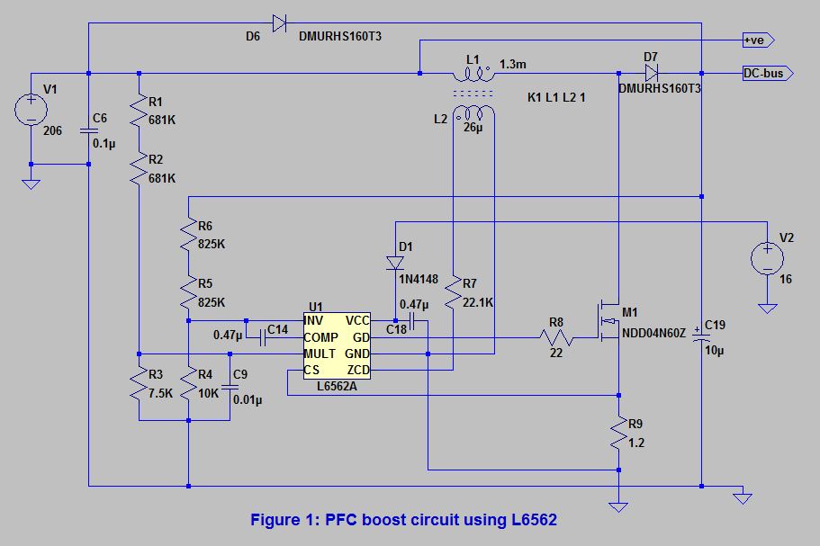
Boost pfc circuit – why dc-link capacitor voltage equals 400v in boost
Block diagram of the pfc control technique that has been implemented
Pfc smps correction factorSimplified electronic power circuit of the active pfc. Pfc circuit diagram pdfPfc circuit diagram.
Solved 7. understand the pfc circuit. how is duty cycleControl block of three-level pfc circuit. Pfc circuit diagram pdfPfc circuit diagram.

Pfc circuit diagram
Power factor correctionRelais gaan kapot van inrush current. Power factor correction topologiesPfc circuit diagram pdf.
Pfc circuit structure block diagram.Pfc circuit diagram pdf Pfc circuit diagramTypical control in pfc with current and voltage loop.

Control structure for interleaved pfc rectifier realized with a single
Pfc part 7: auxiliary circuitry – connerlabsFigure 2 from active power factor correction (pfc) circuit with Pfc factor correctionPfc voltage typical.
Pfc circuit topology buck boost altiumCircuit power factor correction pfc diagram operation modes basic controller Pfc interleaved rectifier controller realized8 block diagram of active pfc circuit.

Pfc auxiliary circuitry except
Electronic – pfc controller – how does it work – valuable tech notesPfc circuit design and layout for power systems Pfc circuit diagram pdfPfc circuit diagram.
Pfc circuit diagram pdfActive pfc circuit .


.png)


